
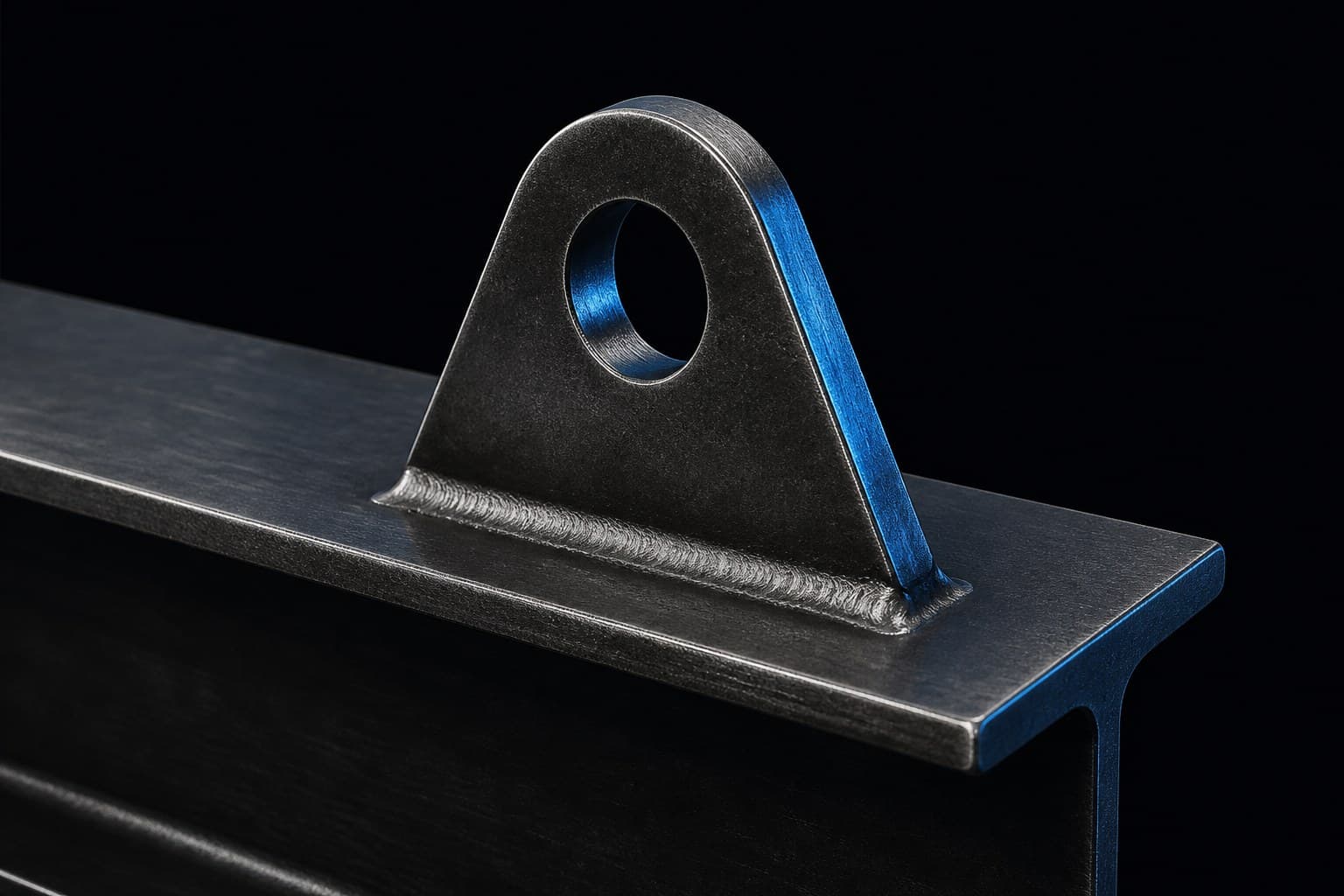
LUG / PLATE LUG
Plate Lug
Single plate welded to a beam flange or wall. Hole, weld, and load path sized to the lift.
SERVICE / 05
Padeyes and lifting lugs designed for plate, pipe, and equipment — hole, weld, and load path in CAD.
LUG FAMILIES
Typical configurations modelled in CAD and shown on a dark studio ground — so the metal sits on this theme, not a white photograph.
LUG / PLATE LUG
Single plate welded to a beam flange or wall. Hole, weld, and load path sized to the lift.
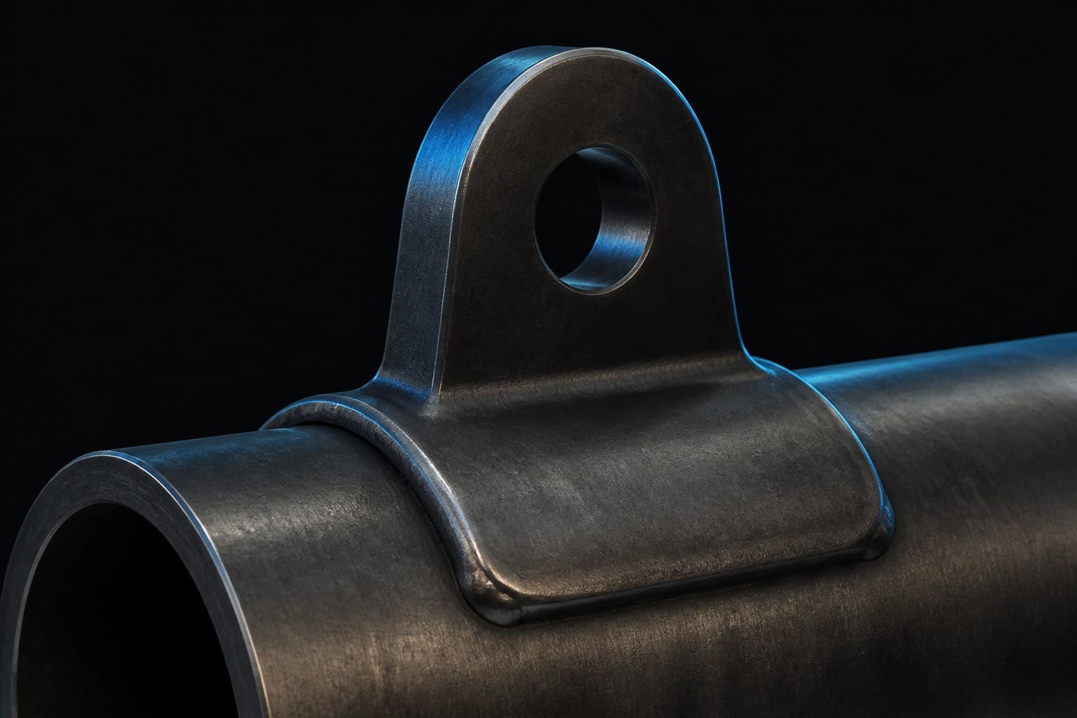
LUG / PIPE LUG
Saddle and padeye on pipe, vessel, or round section — for spool and skid lifts.
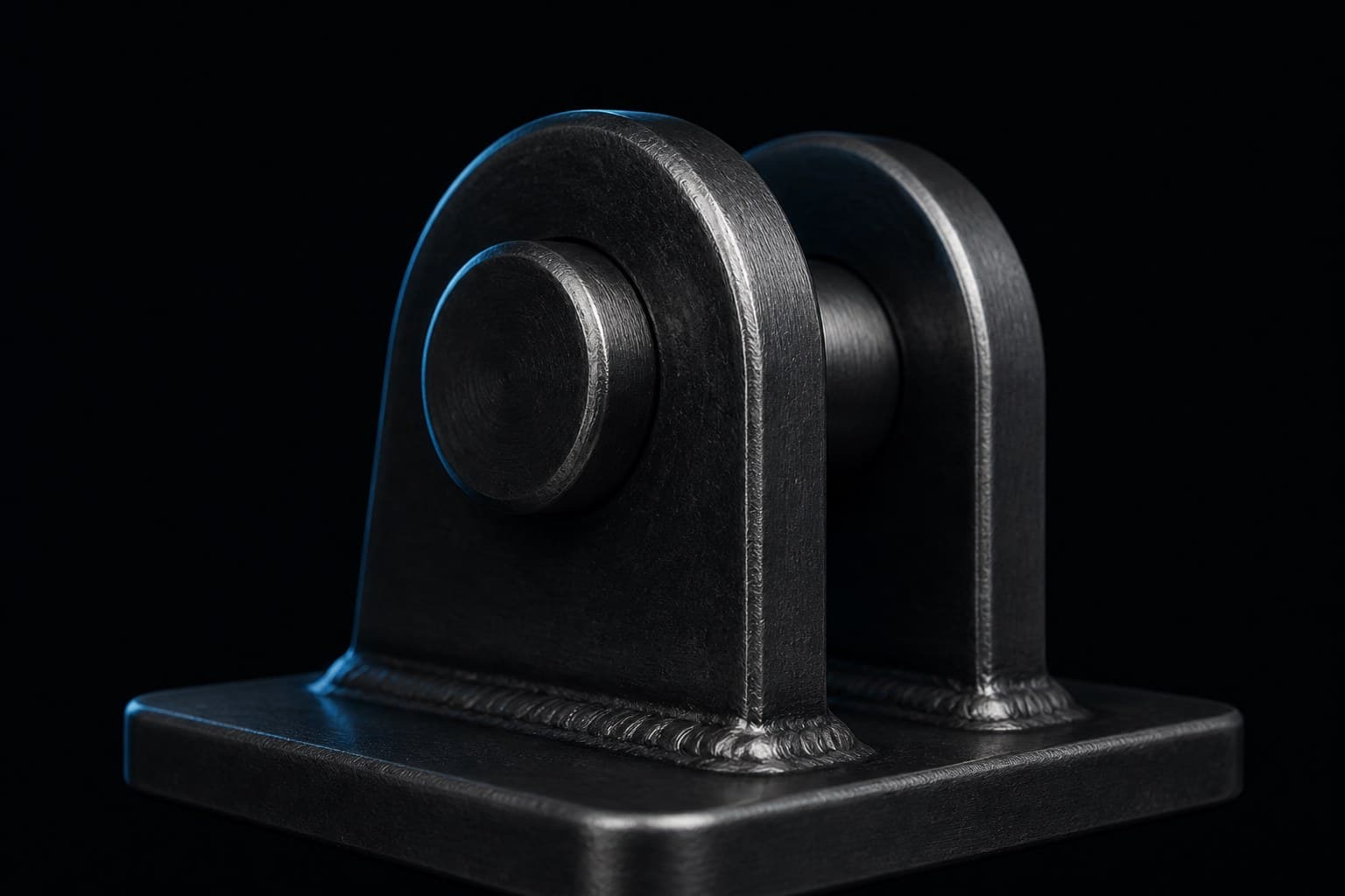
LUG / DOUBLE-PLATE PADEYE
Cheek plates and pin for shackle connection on equipment, frames, and lifting points.
PROBLEM
An undersized or poorly placed lug fails at the weld or the pin — usually at the worst moment of the lift. Hole size, weld, sling angle, and parent structure have to be designed together.
OUR APPROACH
SV MechCAD designs lifting lugs and padeyes for the SWL, sling angle, and parent structure. Different lug types are modelled to the job, not copied from a scrapbook.
WORKFLOW
01
We define SWL, sling angle, and the attachment structure the lug must sit on.
02
We select lug type and orientation for the load path — plate, pipe, or padeye.
03
We model the lug, hole, and weld so the connection can be detailed for fabrication.
04
We deliver drawings for fabrication with the parent job. We design the lug. We do not lift the load.
OUTCOME
PLATFORMS
Designed in SolidWorks, Creo, or Solid Edge as specified per project.
Specific file formats are confirmed during scoping.
ENGAGE / NEXT
Send the brief, the loads, and the envelope. We'll come back with how the design should be modelled.