
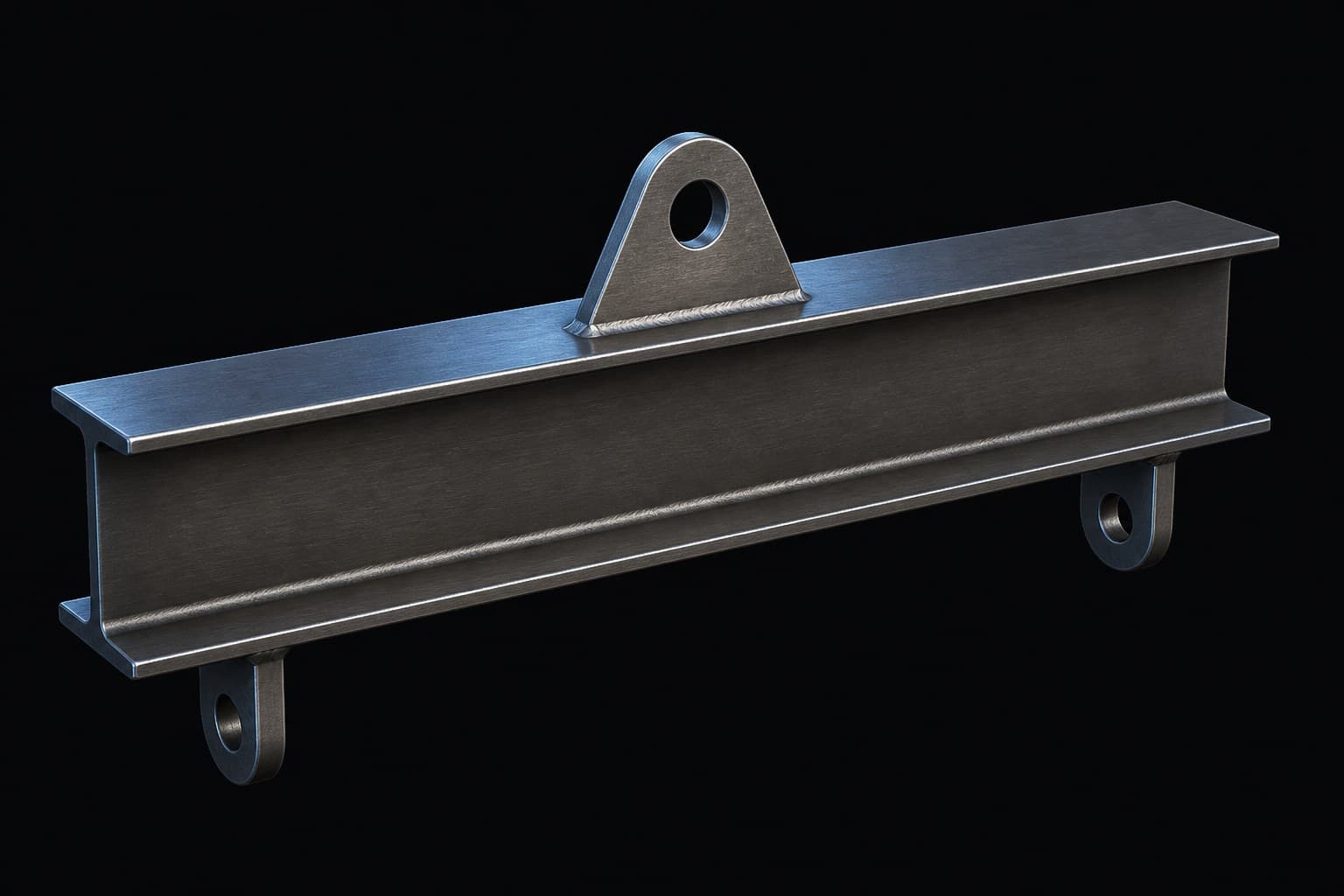
BEAM / LIFTING BEAM
Lifting Beam
Crane hook on the beam. Load hung from bottom lugs — for low headroom and controlled pick points.
SERVICE / 04
Spreader and lifting beam design in CAD — and engineering consultation for the lifting and shifting plan around a critical product.
BEAM FAMILIES
Typical configurations modelled in CAD and shown on a dark studio ground — so the metal sits on this theme, not a white photograph.
BEAM / LIFTING BEAM
Crane hook on the beam. Load hung from bottom lugs — for low headroom and controlled pick points.
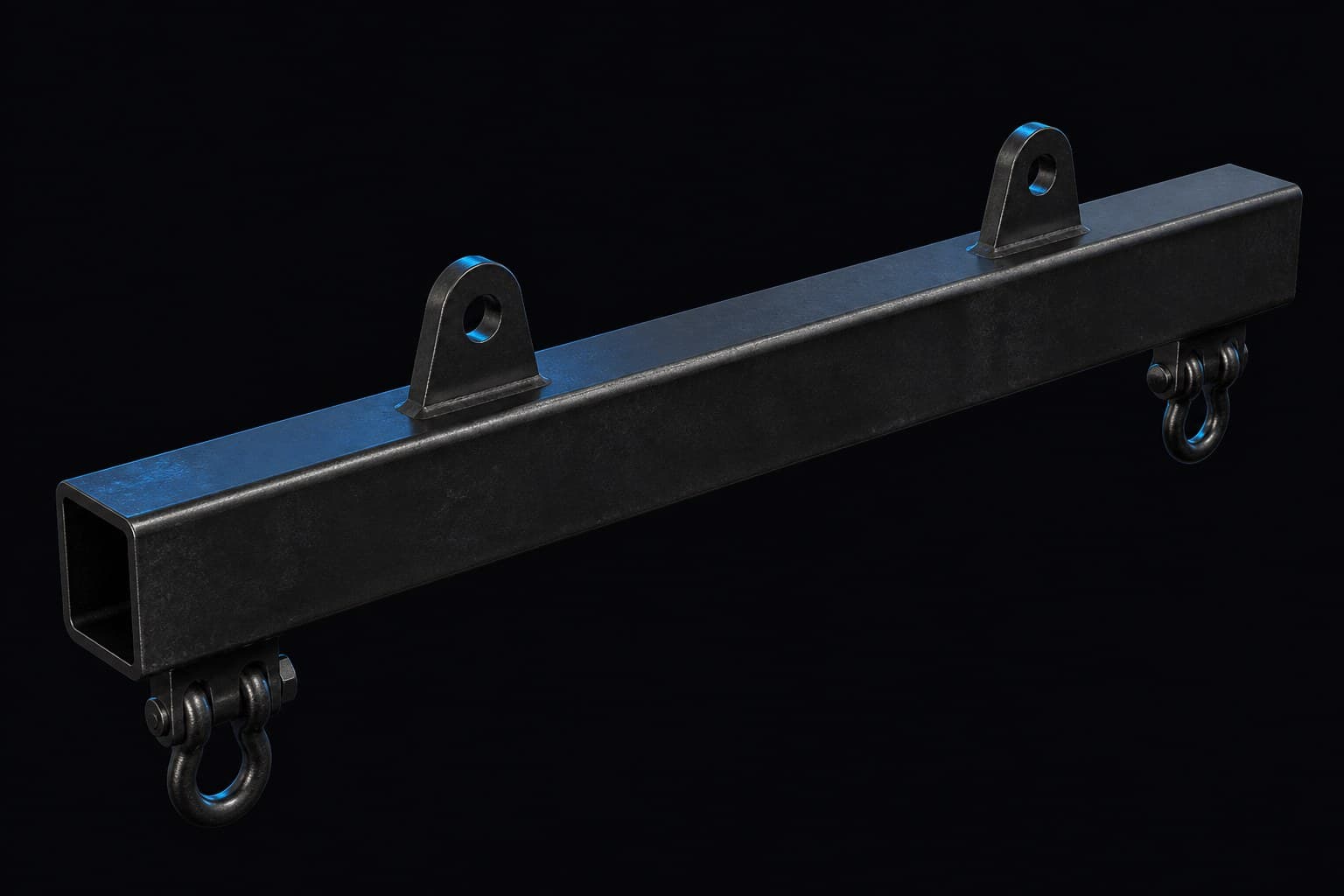
BEAM / SPREADER BEAM
Compression member with slings to the load. Keeps sling angles wide without crushing the cargo.
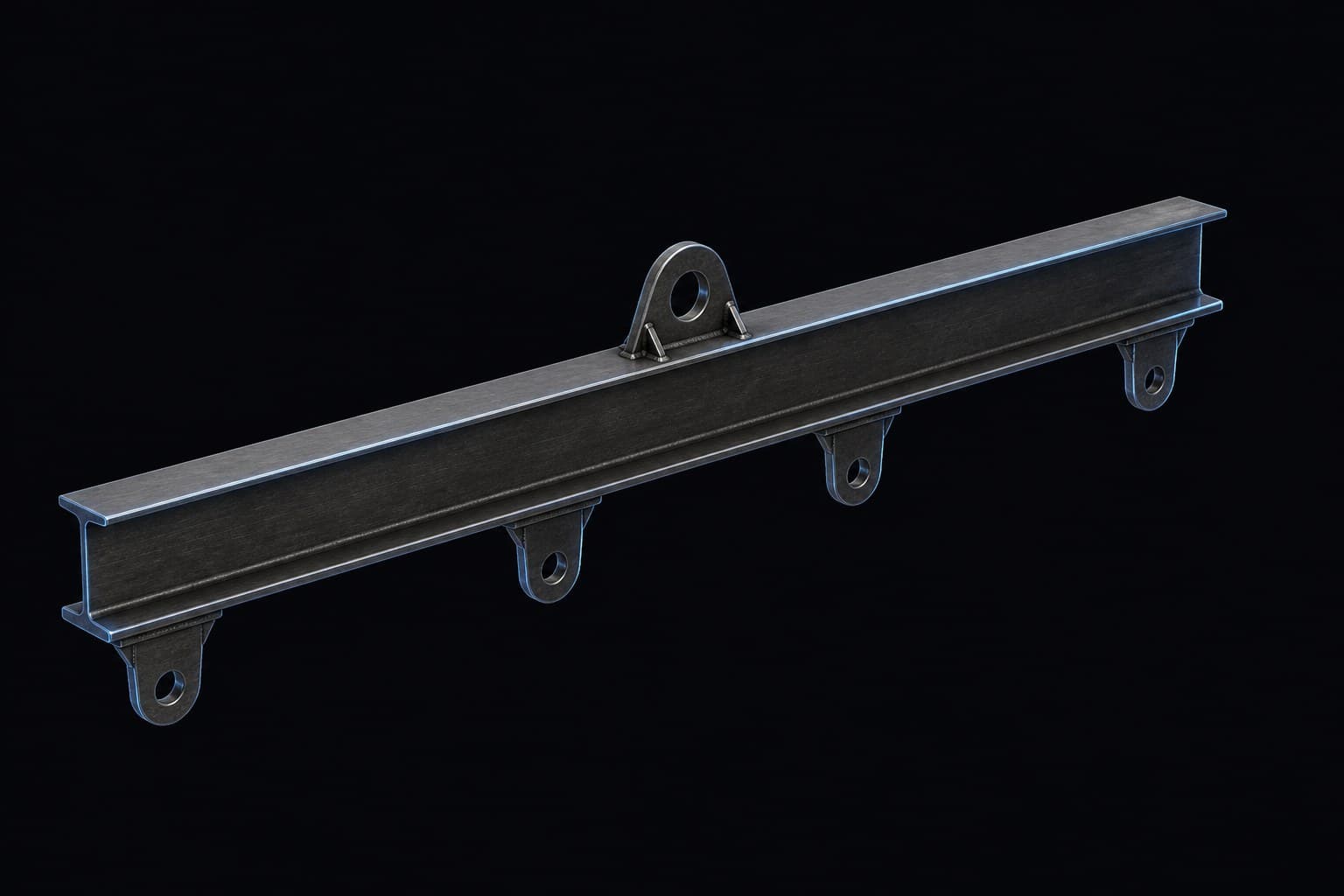
BEAM / FOUR-POINT BEAM
Multiple bottom lugs for wide, long, or offset loads where a two-point pick is not enough.
LIFT AND SHIFT
The beam is one part of the job. We consult on the lifting and shifting plan for a critical product — a complete handling sequence designed in CAD, not a drawing issued in isolation.
PLAN
Pick points, beam type, and crane envelope for the load.
PLAN
How the product is rotated without overloading the beam or the lugs.
PLAN
Moves between rest, lift, and set-down.
PLAN
How the load sits for a move on a special vehicle.
End-to-end design of the handling plan — lift through set-down — for a critical product.
PROBLEM
Different load weights, spans, centers of gravity, lifting points, and crane limitations make a standard lifting beam unsuitable for many applications. An incorrectly designed beam can lead to uneven loading, excessive deformation, or unsafe lifting conditions.
OUR APPROACH
We develop lifting beams based on the SWL, span, center of gravity, lifting points, available headroom, and crane limitations. Each design is customized to the actual lifting requirement rather than relying on a generic configuration.
WORKFLOW
01
We collect load, SWL, span, C of G, lifting points, and equipment constraints.
02
We select the appropriate beam configuration and develop the structural concept.
03
The beam is modelled in 3D CAD, detailed, and checked for structural performance. FEA can be incorporated where required.
04
We provide fabrication-ready 3D CAD models, detailed drawings, and design documentation.
OUTCOME
PLATFORMS
Designed in SolidWorks, Creo, or Solid Edge as specified per project.
Specific file formats are confirmed during scoping.
ENGAGE / NEXT
Send the brief, the loads, and the envelope. We'll come back with how the design should be modelled.